Here’s something that surprises a lot of clients: almost every project we run clash detection on throws up a clash of some kind. Not occasionally. Almost every single one.
Sometimes it’s minor. Sometimes it’s the kind of thing that, if it slipped through, would cost you a fortune to put right on site.
That’s the whole point of BIM clash detection. You find the conflicts on a screen, while they’re still cheap to fix, instead of finding them with a drill and an angry site manager.
I’m Graham King, Managing Director of Terrain Surveys. We’ve been carrying out surveys across England and Wales since 2004, and clash detection has become a core part of the work we do for clients. So let me walk you through how it actually works, what we catch most often, and where projects go wrong.
What is BIM clash detection?
BIM clash detection is the process of scanning a combined 3D model to find where elements collide or interfere with each other before anything gets built.
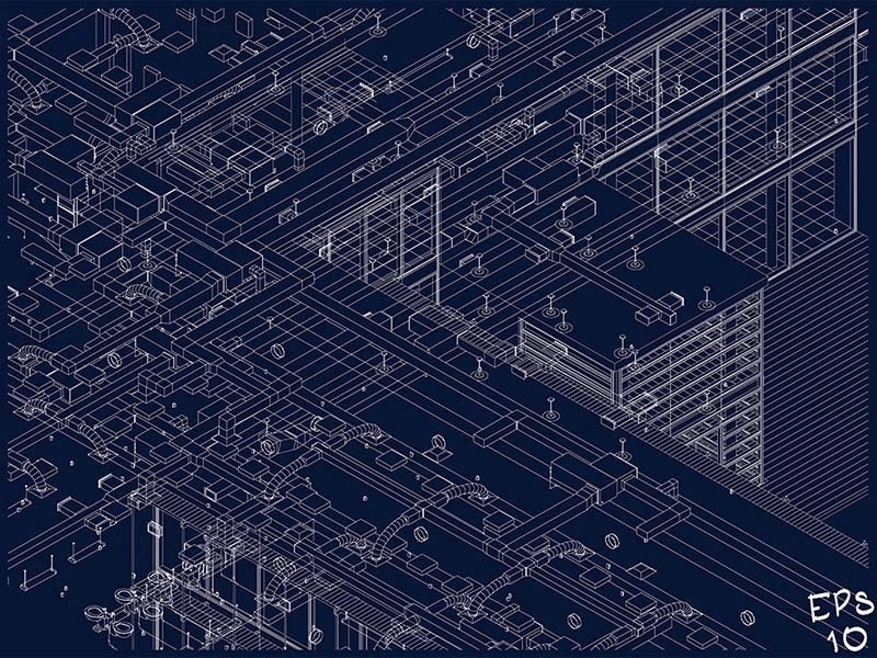
You take the different discipline models (structural, architectural, mechanical, electrical and plumbing) and merge them into one federated model. Then software checks for conflicts.
There are three types worth knowing:
- Hard clash. Two things physically occupy the same space. A duct running straight through a structural beam, for example.
- Soft clash. Nothing physically touches, but a clearance or access rule is broken. A valve with no room to reach it for maintenance.
- Workflow clash. A scheduling conflict. Two trades booked into the same space at the same time.
Hard clashes are the obvious ones. The soft and workflow clashes are where experience earns its keep, because they’re the ones people miss.
Why catching clashes early matters so much
Rework is one of the quiet killers of construction budgets.
The scale of the problem is significant. Research consistently puts the cost of rework at a substantial slice of total project cost, and on a large scheme that’s not a rounding error. That’s real money, most of it preventable.
Did You Know?
Rework typically accounts for somewhere between 5 and 11 per cent of total construction project cost in the UK, with much of it traced back to poor information and coordination errors. A 2023 PlanRadar survey of over 2,500 UK and EU construction customers put the figure at more than 11 per cent. Catching clashes in the model is one of the cheapest ways to claw that back.
Source: PlanRadar, The Cost of Rework in Global Construction (2023), UK & EU survey
Here’s the thing about construction verification work in particular: the tolerances are tight. On some elements of structural framing the tolerance is often just 5mm.
That sounds generous until you realise any error compounds. A few millimetres out at the frame can throw off everything that follows.
So when we catch a problem soon after the element causing it has been installed, whether that’s a structural member or a run of services, it can be put right on site or corrected in the design model before it snowballs. Catch it late and it can prove costly in both time and money.
The clashes we catch most often
It depends on the type of survey, but there are clear patterns.
On as-built models
The most common culprit is MEP (mechanical, electrical and plumbing) services. We regularly find them clashing with builders’ work holes that are in the wrong place, or running into beams and columns that were incorrect or missing from the previous drawings altogether.
The other frequent one is geometry that simply isn’t true. Walls, columns and beams that aren’t straight, either in plan or vertically.
That happens more than you’d think on as-built surveys. The building rarely matches the drawing perfectly.
On construction verification surveys
Again, MEP leads the way. We often find the design model hasn’t been followed correctly during construction, so services clash with features and structure that changed somewhere between design and build.
Then there’s the structural framing, where some elements carry that low 5mm tolerance. Any error there needs flagging as soon as possible, because it can easily affect the rest of the build.
Finding both of these issues early is the entire value of the exercise.
A clash that saved a client serious money
One project sticks in my mind. A large site in London, started before Covid.
The original company liquidated. A new client picked the scheme up and asked us to carry out a BIM survey and verify it against the latest design models.
What we found was alarming. The design model they’d started adding their new details to didn’t match the structure that had actually been built, nearly four years earlier.
Luckily we surveyed early into their involvement. Had they kept building on a model that didn’t reflect reality, the cost would have been enormous. That single check saved them a vast amount of money.
How clash detection works in practice
So how do you actually detect clashes, in Revit or otherwise?
The model itself is usually built in Revit. The clash detection is then run in coordination software such as Autodesk Navisworks or Solibri, which can federate large multi-discipline models and check geometry against the rules you set.
In the UK, this all sits within the ISO 19650 framework, where every discipline shares its model through a common data environment so everyone is working from the same information at the same time. That’s the bit people underestimate. Clash detection is only as good as the coordination behind it.
On projects where we run the clash detection ourselves, we export the clashes as a separate model. Both the main model and the clash model then go up to the Autodesk Construction Cloud project, so every party involved can import and view exactly what’s been flagged.
It puts everyone on the same page, literally. No arguing over whose drawing is right.
That consistency matters when you are doing this at volume. We handle around 500 scan-to-BIM projects a year, which gives us a very clear benchmark for what good, coordinated output should look like.
The mistakes that cost the most
Here’s what most people miss: the expensive BIM mistakes aren’t made during modelling. They’re made at setup.
Three pitfalls cause the most damage:
- Project setup errors. Templates and shared coordinates that aren’t right from the start cause problems on every multi-discipline job.
- No agreed Level of Development. If LOD isn’t agreed upfront, you’ll burn time and money modelling the wrong amount of detail.
- No agreed Revit version. Revit isn’t backward-compatible. Build the model in the latest version and a team on an older one simply can’t open it.
That last one catches people out constantly. It’s an easy fix if you agree it on day one, and a real headache if you don’t.
On the subject of LOD, here’s a misconception we correct regularly: LOD 400 doesn’t mean “more accurate”. It means “more detailed”.
A LOD 300 model built from a quality laser scan will be dimensionally accurate to plus or minus 10mm. A LOD 400 model built from tape-measure data won’t be.
Accuracy and detail are not the same thing. Specify the right one for what you actually need.
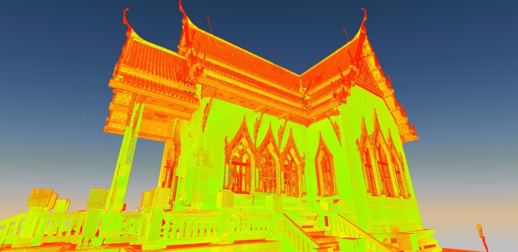
Why 3D and scan-to-BIM are becoming the standard
The biggest change I’ve seen in my career isn’t the instruments. It’s what clients expect us to deliver.
A decade ago, 2D CAD drawings were standard, and clients often wanted hard copies sent out in the post. Now many ask for 3D models as a matter of course.
That shift is exactly why clash detection has taken off. You can’t run a proper clash check on a flat 2D drawing.
The cost case stacks up too. We surveyed a Victorian office conversion with 50 rooms, and the client needed services, fixtures, fittings and reflective ceiling plans on top of the usual floor plans and elevations. In 2D, that’s a minimum of 200 separate elevation drawings just for the rooms.
One 3D Revit model was the cheaper option, easier to manage, and gave the client a single point of truth they could build on over time.
And the direction of travel is clear. We expect demand for scan-to-BIM to grow significantly as retrofit programmes scale up, because for complex projects, 2D simply can’t show enough detail.
Key Takeaways
- Almost every project we run clash detection on finds at least one clash, ranging from minor to severe.
- MEP services clashing with structure is by far the most common issue, on both as-built and construction verification work.
- Structural framing tolerances are tight (on some elements as little as 5mm), so errors must be caught and flagged early.
- The costliest BIM mistakes happen at setup: no agreed LOD, no agreed Revit version, wrong templates.
- LOD 400 means more detailed, not more accurate. A LOD 300 laser-scan model is accurate to plus or minus 10mm.
Get clash detection done properly
Clash detection isn’t a tick-box at handover. Done well, it’s one of the smartest ways to protect a construction budget before a single problem reaches site.
If you’ve got a project where the model and the reality need to match, that’s exactly the work we do. We’re happy to take a look and talk you through the best approach.
Need a BIM Survey or Clash Detection?
Get a free, no-obligation quote from our experienced surveying team across England and Wales.